Home
Pictures
& Descriptions
Array
of Tru-Fit Fittings
Tru-Fit
vs. Prior Types
Pushing
& Pulling Forces
Free Demonstration Video
Play Demonstration Video
About us
Contact us
Tri-Tube, Inc.
Patent
No.: US 7,237,808 B2
Click here for a new but
simple answer to conserving
energy
www.gap-power.com
|
|
Pictures and
descriptions demonstrating
the advantages of Tru-Fit fittings
New |
Old |
The Tru-Fit fitting has a ball type end versus the
previous angled one. The ball or sphere allows
the mating flared tube to align from an axis other
than straight in. This allows for greater
flexibility and permits greater tolerances of
all connecting points. To someone familiar with tube
and pipe fittings and their use the difference will
be obvious.
|
 |
 |
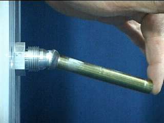 |
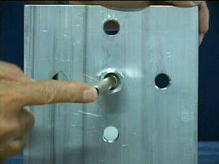
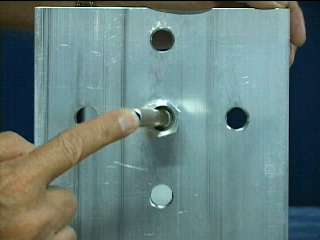
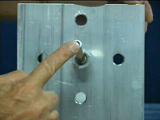
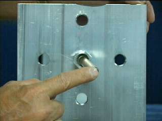
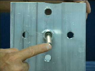
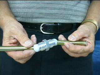
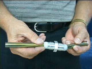
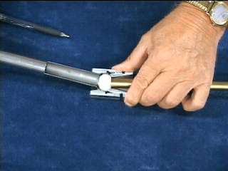
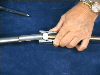
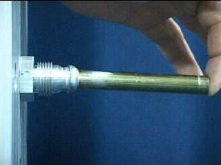
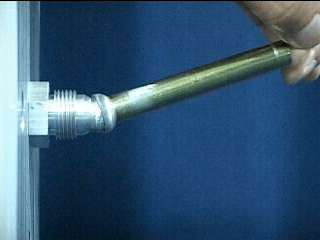
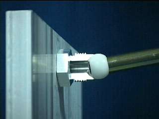
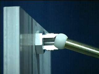
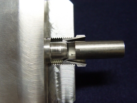
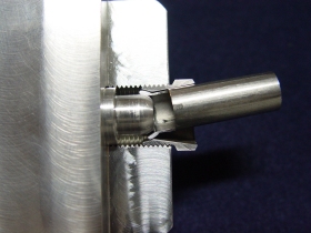
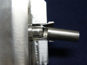
These three pictures display
a tube with the
Tru-Fit design
flare mated to a male fitting.
Note the multi-axis capabilities.
Truly a
specialty fitting.
|
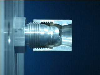
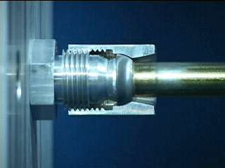
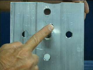
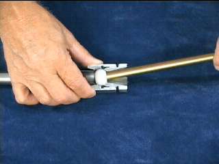
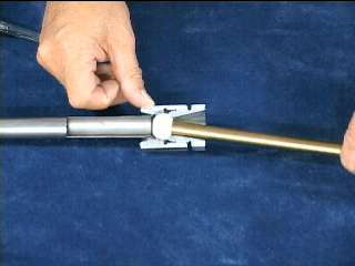
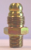
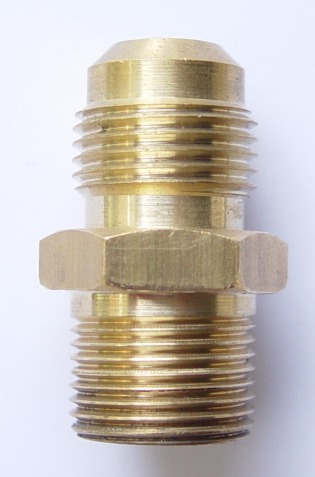
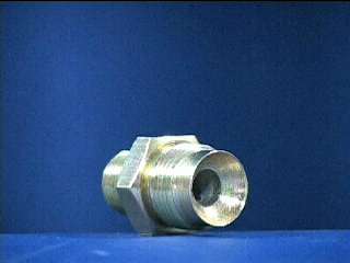
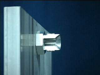
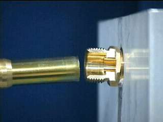
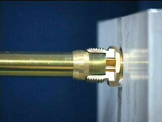
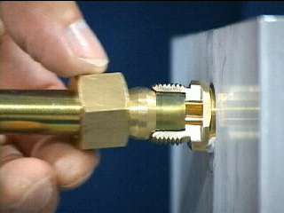
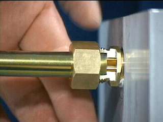
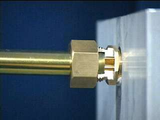
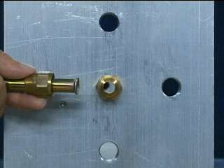
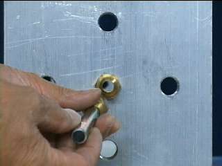
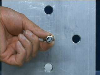
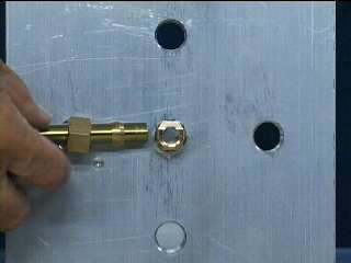
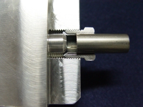
The above four pictures show a male fitting
with a cut-away female nut made with the Tru-Fit
design. Here you can see how the assembly
looks. Note the ball and socket type nature.
The tube has a Tru-Fit
type inverted flare. A special tube
fitting connection using the
Tru-Fit
specialty
fittings.
|
 |
The female version of the
Tru-Fit style
fitting. |
|
 |
 |
 |
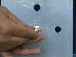
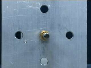
The top-left photograph shows
a cut-away view of the female
version. The other two photos
display the multi-axis
capability
using the Tru-Fit
method. |
 |
 |
 |
 |
 |
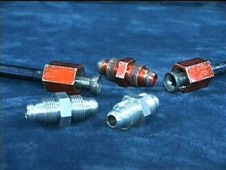
These five pictures show a
previous design fitting, ferrule,
tube, and nut combination.
It does not have the multi-axis
capabilities of the Tru-Fit
design.
The fitting is a cut-away for clarity. |
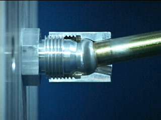
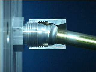
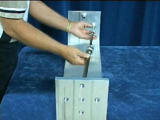
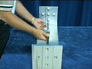
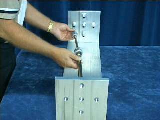
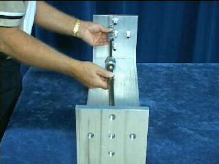
The above six pictures display the multi-axis
rotating ability using a Tru-Fit male fitting, flared tube,
and nut.
|
 |
 |
 |
These three pictures show
a 45 degree flare fitting, tube,
and nut. It doesn't have the
multi-axis rotating ability. |
 |
 |
 |
These three pictures are of a
previous design ferrule type
fitting, nut, and tube. It
doesn't
have the multi-axis rotating
ability. |
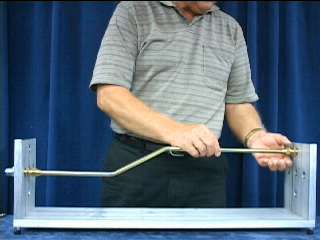
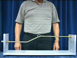
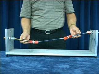
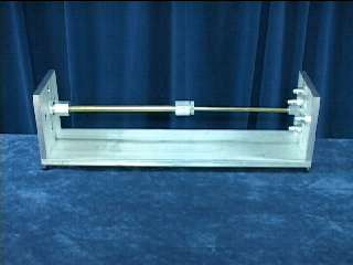
The above four pictures show two off-setting objects
being connected with 45 degree flare fittings and
tube. The tube must have at least two bends in order
to accomplish this. The tube always
almost
fits!
The tube is always too long, too short, or on
the wrong angle. This creates stress between the two
objects being connected. There is always a pushing
or pulling force which creates tension throughout
the connections. By using Tru-Fit fittings
this stress may be eliminated.
|
 |
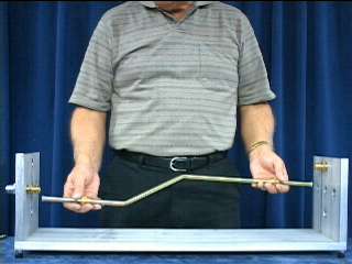
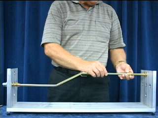
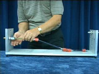
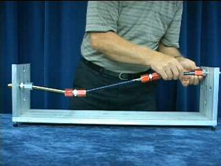
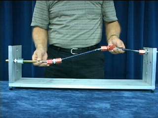
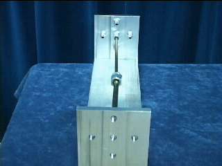
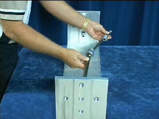
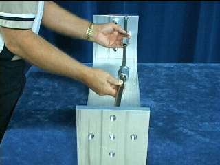
Now, using the Tru-Fit design hydraulic
fittings or air fittings, we will make the
same type of connection as before. |
Bends without
bending.
By using the Tru-Fit method, the same
connection can be made. No bending of the tube is
required using these specialty
tube fittings. Before tightening the fittings, it is very
flexible. After tightening the fittings in the
positions required, the connection is very rigid.
With the Tru-Fit design one may create a
stress-free rigid connection with flexibility.
|
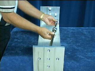
The same connections can be made using the Tru-Fit
ferrule and female fitting design.
Bending tubes without bending.
|
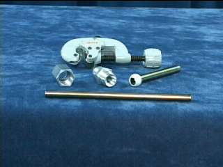 |
Using the Tru-Fit female fitting
and ferrule, the only tool
required
is a simple hand tube and pipe
cutter. This makes it nice for
in-the-field repairs! |
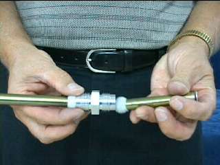
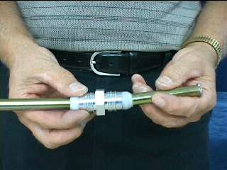
Here we have a cut-away
view of
a
telescoping tube using the Tru-Fit
design tube fittings. The larger tube has
a double flare while the smaller tube
has a ferrule.
Note the design of the fitting and
nut. Both the large and small tube
have multi-axis capabilities. |
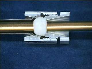 |
With the ferrule at the end of the small tube there
is 20 degrees of axis movement in both tubes.
|
 |
 |
 |
 |
 |
 |
 |
 |
 |
These nine pictures display
the increase in tolerance and
flexibility by using the Tru-Fit
Alignment Solutions
special
fittings. |
 |
This picture displays a 1/2 inch dia. tube
with a standard 45 degree flare and a
standard 1/2 45 degree inverted flare
fitting used in a typical application. Note
the tube has to be directly in line and
has no radial axis capability. |
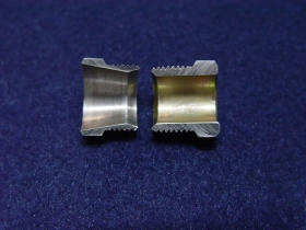 |
The part on the right is a cut-away view
of a standard 1/2 inch 45 degree
inverted flare fitting. The part on the
left is a standard 1/2 inch 45 degree
inverted flare fitting modified per the
Tru-Fit
design. |
 |
This picture shows an inverted flare
fitting and tube of the Tru-Fit
design. |
 |
Note the tube doesn't have to be
directly in line as with the use of the
standard 45 degree inverted flare fitting. |
 |
Note the tube doesn't have to be
directly in line as with the use of the
standard 45 degree inverted flare fitting. |
Click
here to see an array of Tru-Fit fittings. |
|